What makes up a machine vision system?
A machine vision system combines image formation, image analysis, and a way to act on or record the result. Its exact components depend on what must be inspected, how quickly parts move, and how the result fits into the production process. A smart camera may combine several functions in one device; a PC-based setup may use separate cameras, acquisition hardware, processing, and controls.
For a broader introduction to the field and its applications, see Loopr’s machine vision overview. This page focuses on the components and how they work together.
The main building blocks are lighting, optics, a camera and image sensor, image acquisition and triggering, processing hardware and software, and communications or machine outputs. Calibration and mechanical mounting help keep the whole setup consistent. This is a functional map, not a universal bill of materials.
1. Lighting makes the feature visible
The lighting arrangement shapes how a part appears in the captured image. It can make an edge, surface mark, label, hole, or other feature easier to distinguish from its background. Common arrangements include ring, bar, dome, coaxial, and backlighting; the useful choice depends on the part’s shape, surface, material, and the feature being inspected. See KEYENCE’s vision-system overview for the relationship among lighting, lens, and sensor.
Lighting may be continuous or synchronized with image capture. A stable setup matters because changes in brightness, angle, reflections, or shadows can change the image presented to the inspection software. Start by describing the feature to see and the visual conditions that hide it, then test lighting against representative parts and expected variation. A light type alone does not guarantee a successful inspection. For an industry example, see our post on aerospace part inspection challenges.
2. Optics control the view
The lens gathers light and projects an image onto the sensor. Focal length, working distance, field of view, depth of field, aperture, and distortion all affect what the camera can resolve, and the lens mount must match the camera. Filters can limit selected wavelengths or reduce unwanted light when the application calls for them.
Choose optics together with the sensor and the inspection geometry. Sensor size and focal length together set the field of view at a given working distance, so changing one without the other can leave the inspection area too wide or too narrow. A lens that focuses at one distance may not keep the whole inspection area sharp. For dimensional measurements, the setup may also need lens-distortion correction and geometric calibration.
3. The camera and sensor capture the image
The image sensor converts incoming light into electrical signals that form a digital image. A camera packages the sensor with the electronics and interface needed to deliver images. Camera choices can include area-scan or line-scan capture, monochrome or color imaging, sensor size, resolution, frame rate, exposure control, and connection type. Cognex’s component guide describes common lens, image-sensor, lighting, processing, and communication elements, including integrated sensor designs.
The right choice follows from the part and process. An area-scan camera captures a two-dimensional frame at once; a line-scan camera records a narrow set of pixel rows in sequence, which suits some continuously moving products. Basler’s camera-selection guide explains these capture differences. Resolution should be considered alongside field of view, optics, motion, and the smallest feature that must be detected. More pixels by themselves do not establish the measurement capability of a complete system.
4. Acquisition and triggering control when images arrive
The acquisition path moves image data from the camera into the processing system. Depending on the architecture, that path can include a camera interface, frame grabber, network connection, driver, or an integrated smart-camera processor. A trigger can coordinate capture with a sensor, machine cycle, encoder, or other event. A synchronized light pulse may be used when the application requires it. The Cognex In-Sight getting-started documentation illustrates how image capture, lighting, processing, and communication fit into an integrated system.
This stage must deliver images at the rate and timing the inspection requires. When parts move, exposure time and capture timing affect motion blur and the part’s position in the image. The interface and processing capacity must also handle the required image size and rate. Confirm these choices with the complete operating sequence rather than evaluating the camera in isolation.
5. Processing hardware and software interpret the image
Processing hardware may be built into a smart camera, placed in a separate vision controller, or run on an industrial computer. Software applies the configured inspection steps or model to the acquired image. Depending on the task, those steps can locate a part, measure a feature, read a code, compare an assembly, or classify a visible condition.
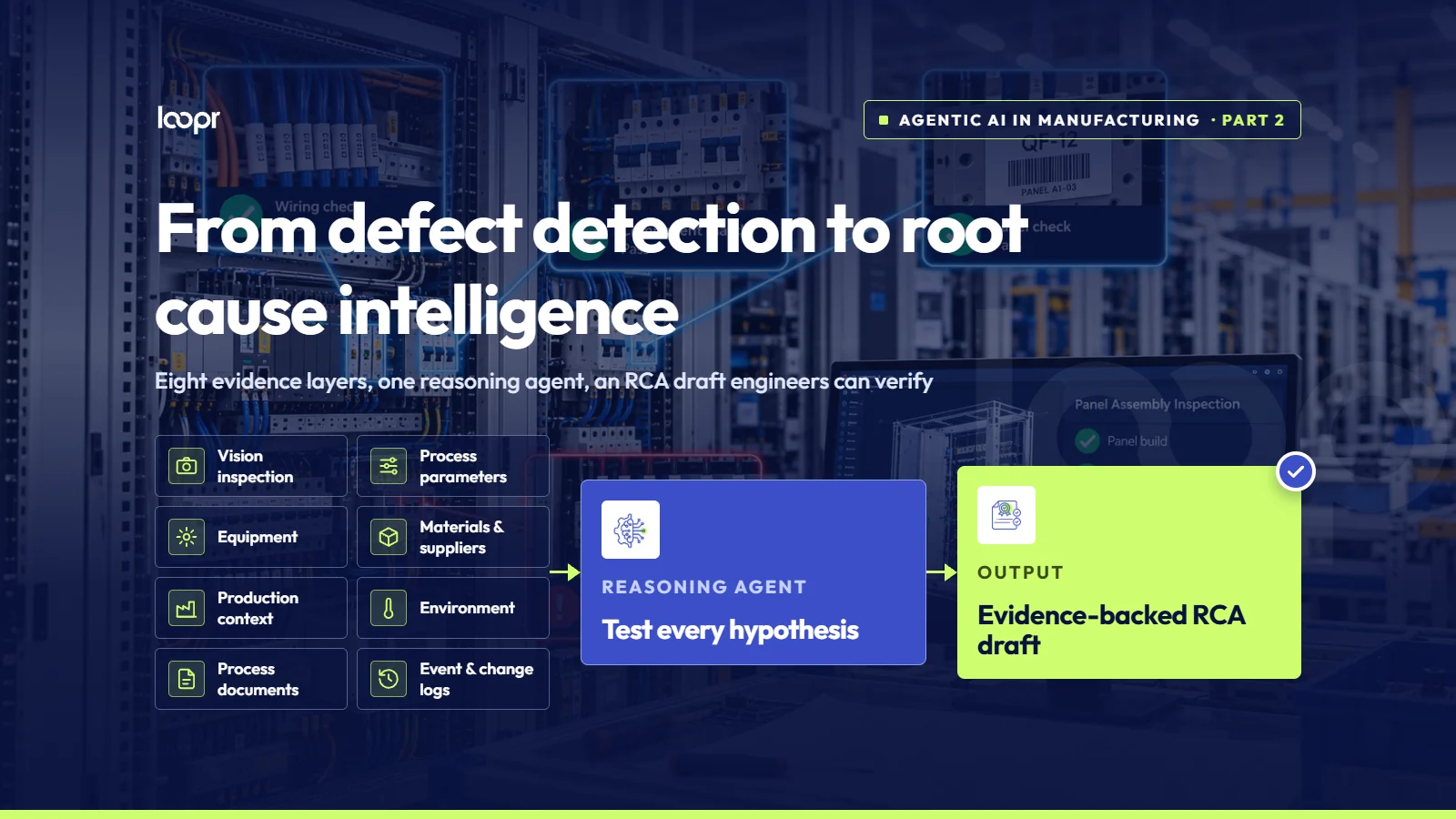
Some inspection software uses trained AI models instead of hand-configured rules, which can help with defects that vary in appearance or are hard to describe with fixed rules. Loopr is a quality intelligence platform for manufacturers that takes this approach: it digitizes inspections, automates visual QC with Vision AI, and keeps audit-ready records for every part.
The output is only as useful as the image and the inspection definition. The system needs a clear definition of the feature of interest, examples that represent expected variation, and a way to verify performance under real operating conditions. Different methods and products have different requirements; no single software approach fits every inspection.
6. Communications connect the result to the process
After analysis, the result may be displayed, logged, sent to a controller, or used by another part of the production system. Depending on the installation, communication can use discrete inputs and outputs, industrial networks, serial connections, or software interfaces. A line controller, programmable logic controller (PLC), robot, or operator interface may consume the result, but the supported connection and required response must be checked for the specific system. The same Cognex documentation gives examples of system communication with a human-machine interface (HMI), PLC, or robot.
Define what the downstream process needs to receive, when it needs the result, and how it should handle missing images, communication failures, or uncertain inspection outcomes. Machine vision produces information; the surrounding automation defines what action follows.
7. Mounting and calibration keep the setup repeatable
The camera, lens, and light need a stable relationship to the part. Mounting, enclosure, cable routing, working distance, vibration, and access for cleaning or maintenance all affect whether the intended image can be captured consistently. Calibration relates image measurements to physical coordinates or corrects known optical and geometric effects when the application requires it.
Calibration is not a replacement for stable mechanics or correct optics. If the camera, lens, part plane, or mounting position changes, the calibration may need to be checked again. Record the assumptions and verification method that apply to the installation.
How the components work together
An inspection cycle can be described as a sequence:
- A sensor or machine event indicates that a part is ready for imaging.
- The camera and lighting capture the feature through the selected optics.
- The acquisition path delivers the image to the processor.
- The inspection software analyzes the image and produces a defined result.
- The system sends, displays, or records the result for the next process step.
Each stage affects the next. If a defect is hard to see in the image, changing the inspection algorithm may not solve the underlying imaging problem. If a result arrives too late, the bottleneck may involve capture timing, transfer, processing, or control integration. Troubleshooting the sequence helps identify which part of the system needs attention. For how these systems fit into a wider quality program, see the role of machine vision in manufacturing quality control.
Questions to answer before choosing components
Write down the smallest feature to inspect, the part’s position and variation, the field of view, working distance, surface and lighting conditions, part speed, required cycle time, environment, result format, and integration constraints. Then test the proposed camera, lens, lighting, acquisition, and processing together with representative parts and operating conditions.
There is no universal component list or specification that guarantees an effective system. The objective is a complete setup that captures a useful image, analyzes the intended feature, and delivers a result that fits the process.
Next step
If you have worked through these questions and want to evaluate AI-based visual inspection for a specific part or line, contact the Loopr team to request a demo.
Frequently asked questions
What is the most important component of a machine vision system?
There is no single most important component for every application. The camera, optics, lighting, timing, processing, and integration have to work together for the inspection task.
Does every machine vision system need a separate computer?
No. Some systems combine image capture and processing in a smart camera or vision sensor. Other designs use a separate controller or industrial computer.
Is a camera the same as a machine vision system?
No. The camera captures an image. A complete system also needs a way to illuminate and image the part, analyze the image, and deliver or record the result.
Does a higher-resolution camera always improve inspection?
No. Resolution is one design input. Field of view, lens choice, lighting, motion, exposure, and the required feature all affect the captured image and inspection.